Recently I had to merge two sites of my lab to one site and therefore from then on I had two /24 networks on that one site, which I had to route traffic between them, because obviously they where located on two sites before and even now they are two separate Layer 2 networks.
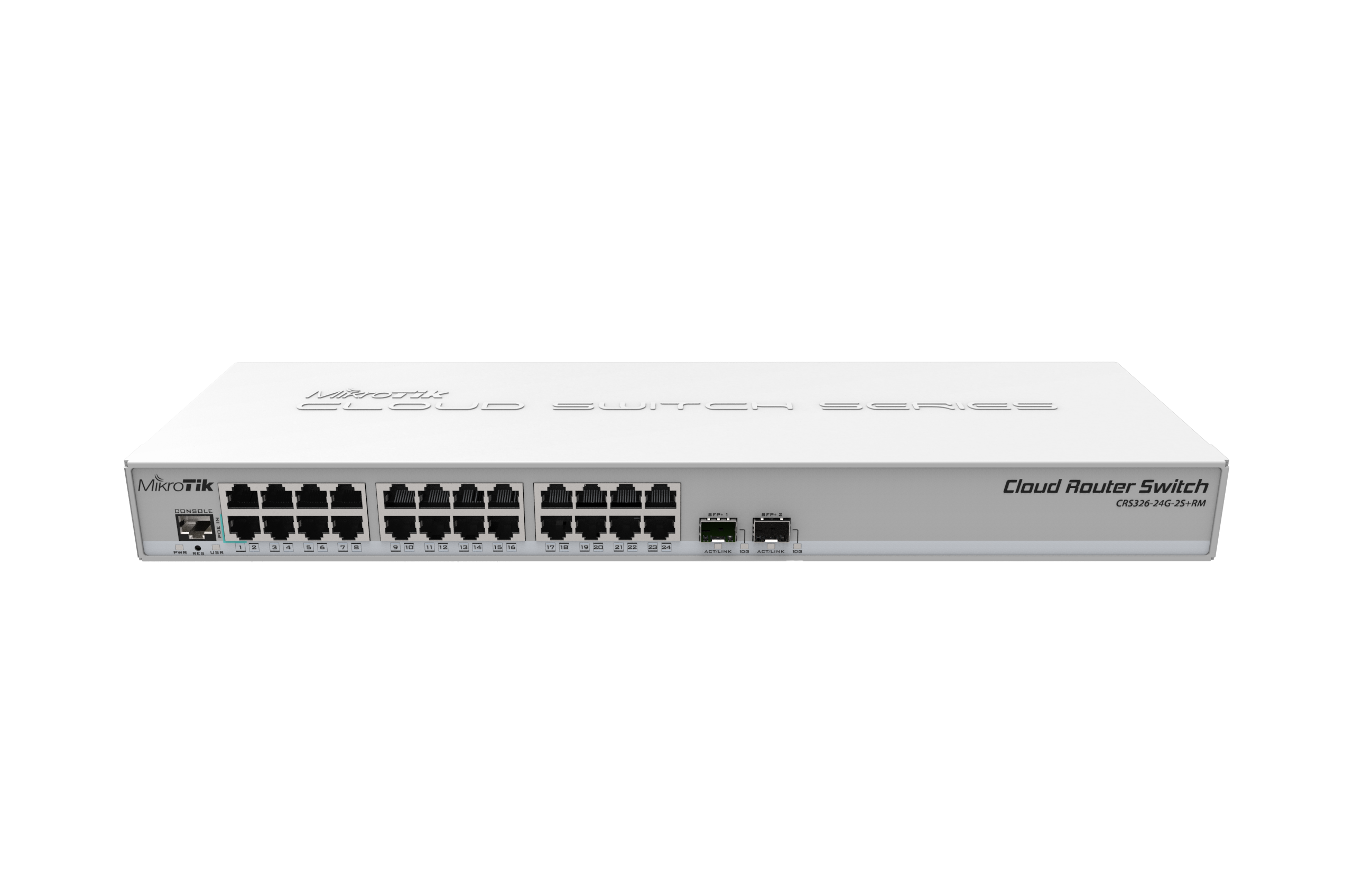
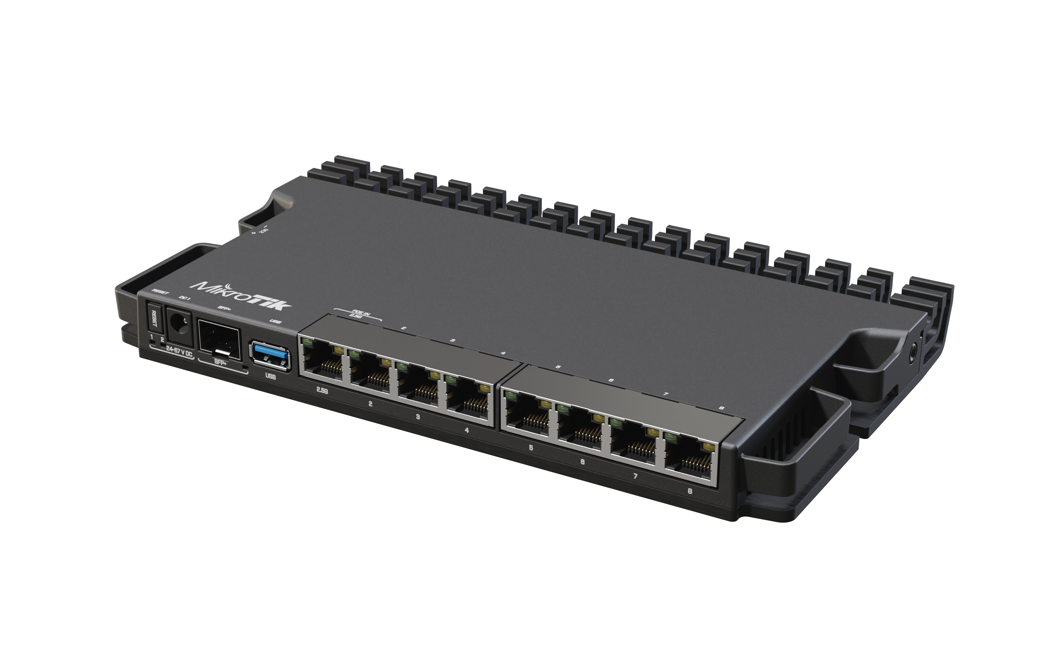
No problem, I said to myself, being equipped with a RB5009UG+S+IN router and a CRS326-24G-2S+RM. Let’s do the routing on the router (duh), since it even has one 10 GbE port, which also serves as uplink to one of the CRS326-24G-2S+RM 10 GbE ports of that switch. My server with both /24 VLANs was connected to the other 10 GbE port of the CRS326.
CRS326-24G-2S+RMRB5009UG+S+IN
As I had everything wired up and configured, I did a simple file transfer between the two networks which the RB5009 now had to route and I also did an iperf3 test with 1-8 parallel streams. Results were rather underwhelming. Maximum throughput I was able to achieve was around 4-5 Gb/s and the poor CPU of my RB5009 hit the wall at nearly 100% load. So I tried to find and enable L3 hardware offloading and had to learn, that the RB5009 currently (and likely never will be) capable of that.
“What kind of router is that?” I asked myself and went on the MikroTik forums. There I was told that the purpose of the RB5009 is more LAN/WAN routing, NATting and firewalling, than intra-VLAN routing. and that I’d be better off with a proper Layer 3 switch for that purpose. “I’ve got something like that”, I thought to myself and immediately made plans to move the routing of the two /24 subnets from the RB5009 to my CRS326. When I was done with that, I ran some iperf3 tests again and the results were even more underwhelming. I only got around 1-2 Gb/s and the CPU of the CRS326 switch was almost at 100%, just like the RB5009 CPU was.
But then, L3 hardware offloading came for the rescue. I enabled that feature, restarted the switch, just to be sure and clear all the sessions, caches and tables, and started new iperf3 tests. Finally, I was overwhelmed, what a 200$ switch can do, and how incredible it is, that MikroTik added so much value after many years after the hardware release by implementing L3 hardware offloading to this budget switch with RouterOS 7.1, but see for yourself:
one connectionfour connectionseight connections
And that wasn’t even with any optimizations like jumbo frames.
It seems, that the CRS326-24G-2S+RM utilizes the same switch chip as the favourite lab 10 GbE switch of all times, the CRS305-1G-4S+IN, whis is the 98DX3236. Most likely it will be capable of the same performance and possibilities. EDIT: Yes, confirmed. I was able to achieve the same kind of performance with the CRS305-1G-4S+IN.
Being that my newest acquisition is a CRS309-1G-8S+IN, which utilizes a more powerful CPU, the dual core 98DX8208, I’ll probably move routing of the two subnets there and do another set of iperf3 tests. But that’s for another day.
One-Time
Monthly
Yearly
BUY ME A COFFEE (AKA Make a one-time donation)
Make a monthly donation
Make a yearly donation
Choose an amount (meh coffee, good coffee, exquisite coffee)
¤1.00
¤2.00
¤3.00
¤5.00
¤15.00
¤100.00
¤5.00
¤15.00
¤100.00
Or enter a custom amount
Your contribution is appreciated. Coffee will eventually turn into more hopefully useful posts.
In one of my earlier posts (MikroTik IPSEC VPN vendor interoperability), I mentioned the lack of VTI (Virtual Tunnel Interface) support of RouterOS, which is the OS powering our beloved MikroTik routers. That means, you don’t get a virtual interface per VPN tunnel which in turn means you can’t create static routes and interoperate with, let’s say a FortiGate, which has a VTI tunnel configured on its side, and push traffic from your MikroTik router through the FortiGate, to some third, not directly to your MikroTik router connected site. Or can you!
Yes, you can. Sort of.
Imagine the following scenario:
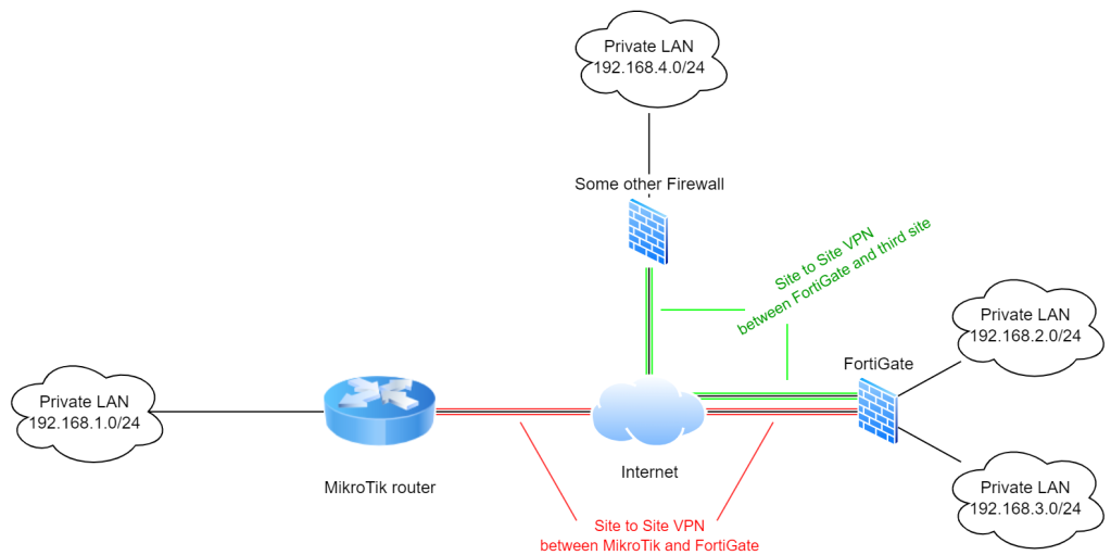
MikroTik router connected to a FortiGate which has connections to multiple LANs. Locally and via another Site to Site VPN, our MikroTik isn’t aware of at all
So in this scenario, our MikroTik router has an IPSEC Site to Site connection to a FortiGate, which in turn has two local (routed) LANs 192.168.2.0/24 and 192.168.3.0/24 and which also has a Site to Site connection to a third Site, with some other Firewall (doesn’t matter which one, because the FortiGate is doing the VPN tunnel stuff, our MikroTik knows nothing about it). That third site has a local IP subnet of 192.168.4.0/24.
We now want our LAN network 192.168.1.0/24, which is behind our MikroTik router, to be able to access 192.168.2.0/24, 192.168.3.0/24 and 192.168.4.0/24, all through that single Site to Site VPN connection between our MikroTik and FortiGate (red in the diagram), without creating a Site to Site connection between the MikroTik and the “Some other Firewall”.
So our FortiGate has this tunnel configuration to our MikroTik router, which is a bog-standard IPSEC tunnel with virtual tunnel interface (VTI):
config vpn ipsec phase1-interface
    edit "MT-LAB"
        set interface "internal1"
        set ike-version 2
        set keylife 28800
        set peertype any
        set proposal aes256-sha512
        set localid "FGT-MTLAB"
        set dpd on-idle
        set dhgrp 5
        set nattraversal disable
        set remote-gw WAN-IP-OF-MIKROTIK
        set psksecret oursecret
        set dpd-retryinterval 5
    next
end

config vpn ipsec phase2-interface
    edit "MT-LAB_P2"
        set phase1name "MT-LAB"
        set proposal aes256-sha512
        set dhgrp 5
        set auto-negotiate enable
        set keylifeseconds 1800
    next
end
Of course, the FortiGate has another tunnel configuration for the Site to Site tunnel to the “Some other Firewall”, but that’ll be just another VPN tunnel configuration, just like this one, nothing special. Also, on the FortiGate you need to create firewall policies to allow traffic from the MT-LAB virtual interface to the two internal networks (which probably have their own interfaces), as well as to the third site’s Site to Site VPN tunnel, which will probably have another virtual tunnel interface (VTI).
On the MikroTik router, the VPN configuration looks like this:
And that’s it. Instead of routes for a virtual tunnel interface (VTI) like on a FortiGate, with tunnel-mode VPN without VTI support on MikroTiks, you just create additional IPSEC policies. Of course, you need to create appropriate NAT rules as well, if your MikroTik router is doing src-nat or masquerade, and also mind your fasttrack (exception) rules, as always with IPSEC on MikroTiks.
Bonus: Imagine you have, additionally to the diagram above, another Site to Site VPN connection from your MikroTik to another Firewall (doesn’t matter if MikroTik or different vendor), and you want to allow traffic from the FortiGate-connected networks to that network:
Third site, connected to our MikroTik router
If you now want your networks behind the FortiGate (192.168.2.0/24, 192.168.3.0/24, 192.168.4.0/24) to be able to reach 192.168.5.0/24 through the red Site to Site VPN tunnel too, just add the following IPSEC policies on your MikroTik router which has the 192.168.1.0/24 network:
As you can see, you need IPSEC policies in all directions. You want to encrypt traffic coming from the FortiGate networks (first three policies) with the Site to Site VPN tunnel which is going to the “Another MT router” and you want to encrypt traffic coming from the “Another MT router” network to all the FortiGate networks (last three policies).
Of course this can get quickly get out of control and it is not a big joy to have a ton of IPSEC policies but currently I’m not aware of a different method, if you want to stick with VTI on the Third Party endpoint (in this case, our FortiGate).
You could of course to get an interface on your MikroTik router also utilize an IPIP tunnel or GRE over IPSEC , which FortiGates even support, however that would mean lower throughput on the MikroTik side because additional processing is required for encapsulating data into GRE or IPIP tunnels. Also, sometimes you don’t have a choice and just have to connect to some endpoint which is doing routed IPSEC aka IPSEC VTI.
Conclusion
Interoperability with other VPN gateways and firewalls which are doing routed IPSEC aka IPSEC VTI, is kind of possible, as long as you don’t want to send Multicast or Broadcast traffic through that tunnel. However it is not fun and can get out of hand quickly, in more complex scenarios and all we can do for now, is to hope that MikroTik hears us and at some point in time will implement VTI in RouterOS.
One-Time
Monthly
Yearly
BUY ME A COFFEE (AKA Make a one-time donation)
Make a monthly donation
Make a yearly donation
Choose an amount (meh coffee, good coffee, exquisite coffee)
¤1.00
¤2.00
¤3.00
¤5.00
¤15.00
¤100.00
¤5.00
¤15.00
¤100.00
Or enter a custom amount
Your contribution is appreciated. Coffee will eventually turn into more hopefully useful posts.
As of writing this post, MikroTik still hasn’t released any numbers or much information on the IPSEC performance and hardware offloading support of the new and fancy RB5009UG+S+IN router.
I however got my hands on one and did some testing. And I am pleased.
Whether your IPSEC tunnel is hardware offloaded or not, you can determine looking at the “H” flag when typing the following command:
/ip/ipsec/installed-sa/print
Winner, winner, chicken dinner, if it looks like this:
Hardware Offloading
Maybe you already have spotted it – aes-cbc and sha512 has hardware offloading support, that’s amazing!
I have tried from 3des-SHA1 for both proposal and profile, through AES256-CBC/SHA512 up to AES256-CTR/SHA512, it always showed me the H flag for hardware offloading and always but once* delivered around 800 Mbit/s throughput, which is kind of high, for that kind of encryption strength. Compared to the hEX, which only supports up to SHA256 for hardware offloading and with that “only” achieves around 360 Mbit/s, that is a nice improvement, especially for that price point.
AES-GCM however is a funny story, which kind of makes me wonder whether traffic is actually even hardware offloaded. If I configure AES256-GCM for the proposal, the “H” flag is gone, but I still get around 800 Mbit/s throughput. The difference however is that, with AES-CBC and AES-CTR the CPU load is around 40-50% and with AES-GCM around 50-60%. According to the CPU profiler, the CPU is busy with networking and ipsec, no matther what algorithm I chose.
* it seems that with 3des-sha1, throughput is limited to something about 180 Mbit/s, despite the fact that the “H” flag is shown. But meh, who wants 3des-sha1 anyway, right?
Firmware
As of RouterOS 7.1rc3, MikroTik seem to have added “hardware acceleration support for RB5009”. I am currently running version 7.1.1 so according to my understanding of version numbering, that hardware acceleration support should be now built in for my RB5009 with RouterOS 7.1.1. However there may still be some optimization to be done and there may be a reason why MikroTik hasn’t released official numbers on IPSEC throughput performance for the RB5009 yet.
Conclusion
But anyway, the current numbers I got don’t look too bad, if you don’t look at the RB4011iGS+RM, which should deliver 2.000 Mbit/s, according to official MikroTik numbers (with SHA256, though – don’t have any numbers on SHA512, although it has hardware support for it). As I was able to achieve 360 Mbit/s with the hEX, which is exactly what they say in their official numbers for AES-256-CBC + SHA256, I believe I would also achieve 2.000 Mbit/s with the RB4011iGS+RM and given that the new RB5009 model is newer and has a similar-specced CPU (even 64 bits!), I reckon that it should in the end, when MikroTik is done with their optimizations, should achieve at least the same speed as the RB4011iGS+RM. If not, that’d be kind of a bummer, given that they advertise it as “The ultimate heavy-duty home lab router”.
For those who are curious, for all of my throughput tests I use iperf3 with no special settings. The only thing I usually do, is to add the “-P 4” parameter, so I get 4 parallel streams.
One-Time
Monthly
Yearly
BUY ME A COFFEE (AKA Make a one-time donation)
Make a monthly donation
Make a yearly donation
Choose an amount (meh coffee, good coffee, exquisite coffee)
¤1.00
¤2.00
¤3.00
¤5.00
¤15.00
¤100.00
¤5.00
¤15.00
¤100.00
Or enter a custom amount
Your contribution is appreciated. Coffee will eventually turn into more hopefully useful posts.
Just a quick heads-up to note one experience I made with my hEX router and IPSEC through a VLAN.
I had my hEX router connected via a physical interface to my LAN network, where I had created a VLAN interface (of course not bridge mode VLAN, as that’s not hardware offloaded on the hEX, if you’re using ROS 6.x). That VLAN interface had an IP address configured, which was designated to be the endpoint of an IPSEC site to site tunnel. The other endpoint was a CHR virtual machine (i had this set up just for experimenting and testing).
No matter what I did, I was only able to get around 100 Mbit/s through that VPN tunnel, although I paid attention to only utilize encryption which the hEX has hardware offloading support for.
Eventually I decided to connect a dedicated, physical interface of the hEX router to that particular network where the other VPN endpoint resided and voila, I immediately got, without changing anything else, around 360 Mbit/s of throughput.
I honestly don’t know what disturbed the hEX router here, I guess it wasn’t the routing because removing that one, now dedicated, physical interface from the bridge and dedicating it for the VPN tunnel in the end didn’t change anything in terms of routing. The hEX still had to route the traffic from my LAN on the bridge to the dedicated interface, which obviously has a different IP subnet. I guess it may have to do with the fact, that the hEX had to add VLAN tags to each and every packet after encrypting it, to be able to send it out on that interface in a tagged way.
If anyone knows, let me know in the comments.
One-Time
Monthly
Yearly
BUY ME A COFFEE (AKA Make a one-time donation)
Make a monthly donation
Make a yearly donation
Choose an amount (meh coffee, good coffee, exquisite coffee)
¤1.00
¤2.00
¤3.00
¤5.00
¤15.00
¤100.00
¤5.00
¤15.00
¤100.00
Or enter a custom amount
Your contribution is appreciated. Coffee will eventually turn into more hopefully useful posts.
Today I’m going to share my thoughts on MikroTik IPSEC interoperability with vendors and why I don’t like it.
This week I took a closer look at IPSEC VPN (no L2TP, no GRE, no whatever) between MikroTiks and more or less immediately I felt reminded about earlier days with Fortigates (which is the world I’m mainly coming from). After you create your IPSEC configuration on the MikroTiks, traffic just flows through the VPN and that’s it. I though to myself: “wait, what? I didn’t create any routes, where are my virtual IPSEC tunnel interfaces? why is this worki… oh.”. It was now obvious to me, that this was tunnel mode VPN without interfaces. Knowing that I have been doing that with Fortigates over a decade ago and that I didn’t like it their either, I was not very thrilled.
To be honest, I didn’t even know what the term for interface based tunnel mode VPN was. I was searching the internet, stumbling upon the two main IPSEC modes of operation “transport mode” and “tunnel mode”, learning that I kind of want transport mode but without disclosing the original IP header to the public, me was confusion.
In the MikroTik forum, a fellow member pointed me into the right direction. What I wanted, what I was doing for years now, not even knowing what it was called, was routed IPSEC aka VTI, which means “Virtual Tunnel Interface”, which makes sense.
Now, that I knew the correct term, the fog cleared up. I found many posts and threads in the MikroTik forum about people complaining that RouterOS doesn’t support IPSEC VTI. I learned from all the posts, that with RouterOS 6.x and earlier it wasn’t possible due to the underlying Linux 3.3.x kernel. Some people mentioned that VTI support may come with RouterOS 7 (based on Linux kernel 5.6 now, afaik) and even that they’ve heard vague statements from MikroTik stating that it may come with RouterOS 7. Unfortunately the only statement which was quoted word by word from a MikroTik support ticket response said that they currently do not have any short-term plans for implementing VTI in RouterOS. That doesn’t mean that it won’t ever come, but it does say that it probably will take a while. That was a major bummer for me.
If you have a bunch of sites connected to each other and you want to do a fully-meshed VPN, maybe even with a dynamic routing protocol like OSPF, you are stranded. Especially, if that “private cloud” consists of VPN endpoints from different manufacturers. In that case, MikroTik can’t get involved, because you won’t be able to integrate a MikroTik router into a network like this, if you are bound to use tunnel mode IPSEC and something like OSPF.
There is a little ray of light however, if you do not rely on a dynamic routing protocol and therefore don’t necessarily need a virtual interface on your MikroTik router. See, VTI mostly(!) is only a “local” thing, so your MikroTik router should still be able to participate in such a meshed network of different vendor gateways, if you do not rely on a dynamic routing protocol and if you do not need to transfer multicasts or broadcasts over your VPN, because that’s something which VTI would be needed for, if you can’t or don’t want to utilize something like GRE over IPSEC.
To achieve that, you “simply” need to add IPSEC Policies on the MikroTik routers, like if you were creating IP routes on a VTI network. Lets say we have three sites:
Site A local network: 10.0.1.0/24 Site B local network: 10.0.2.0/24 Site C local network: 10.0.3.0/24
You need to access site Site C from Site A through Site B, because A and C are not directly connected (for whatever reason) and vice versa, so you create the following IPSEC policies (additionally to the existing policies which exist for A<->B and B<->C connectivity):
Of course, you also need to make sure that your to-be-encrypted traffic is not being catched by your src-nat rule or by fasttrack (if you don’t want that), just like any other IPSEC traffic. Just create corresponding NAT and RAW rules with the appropriate IP subnets as source and destination:
On Site B you do not need any NAT or RAW firewall rules, because on that Site, traffic is just going to faciliate the existing IPSEC tunnels and the firewall of Site C will only see ESP packets flying around between the tunnels to Site A and Site C.
Conclusion
To wrap it up, it seems to be kind of possible to use MikroTiks in an environment where Ciscos, Fortigates and others are using VTI, as long as you don’t need an interface for OSPF or a different dynamic routing protocol, and as long as you are not planning to send multicast or broadcast through that tunnel. Nonetheless, I find it to be a bit sad, that something others have been doing for so long, is still being ignored by MikroTik so badly, despite the obvious demand in the community (which are their customers, in the end).
The tenor in the MikroTik forum, the various communities and from MikroTik support themselves seems to be to “just” use GRE over IPSEC or IPIP within IPSEC or L2TP/IPSEC. But if you can’t or don’t want to do that, you’re stranded. Also, don’t forget that the performance indicators for IPSEC throughput on MikroTiks webpage have been measured with pure IPSEC VPN and are not to be guaranteed if using any other additional feature or function (like GRE or IPIP tunnel). I have seen posts in the forum about users complaining about serious performance drops when using e.g. IPIP within an IPSEC tunnel, compared to plain IPSEC.
One-Time
Monthly
Yearly
BUY ME A COFFEE (AKA Make a one-time donation)
Make a monthly donation
Make a yearly donation
Choose an amount (meh coffee, good coffee, exquisite coffee)
¤1.00
¤2.00
¤3.00
¤5.00
¤15.00
¤100.00
¤5.00
¤15.00
¤100.00
Or enter a custom amount
Your contribution is appreciated. Coffee will eventually turn into more hopefully useful posts.
SSTP VPN is a proprietary VPN technology made by Microsoft which has been around for quite some years (for over a decade in fact). It tunnels PPP over a HTTPS connection which in turn is secured by TLS. With SSTP using standard HTTPS and TLS protocols, Microsoft tried to overcome the issues with traditional PPTP or L2TP over IPSEC VPN tunnels, which often are blocked by various internet access gateways used by the end-users (e.g. in a hotel).
Currently I am not aware of any SSTP server implementations other than Routing and RAS services (which are included in Microsoft Windows Server) since Windows Server 2012 and the one from RouterOS in MikroTik routers. As not everyone can or wants to utilize a Windows Server for this task, I decided to take a look at MikroTiks approach.
At the beginning of this journey, one limitation of RouterOS was not immediately obvious to me: Authentication via EAP-TLS is not possible, so we will have to work around that by using MSCHAPv2 instead. MikroTiks answer to my question why it is not implemented and as of writing this post there are no plans of implementing it was, that SSTP is quite slow (aka resource intensive) already and that all the traffic is being secured by TLS anyway, so I guess they said “bugger that” and sticked with MSCHAPv2.
The goal
At the end of this post we want to have a MikroTik hEX router serving an SSTP VPN server for a Windows 10 client to do Windows Always On VPN. For this time, we will deploy a so called “User Tunnel” instead of a “Device Tunnel”. The difference is, that a User Tunnel comes up automatically only after the correct user has logged on to the client system. A device tunnel on the other hand is meant to be up and running as soon as a computer has completed booting the operating system, before any user logs in.
Given the state my current lab environment which already has a Internet-facing firewall (Fortigate 60D in this case) plus the fact that a MikroTik hEX router does not have too much power when it comes to excessive firewalling, I have decided to put the MikroTik router into DMZ networks of my firewall. This design allows me to do all the firewalling on my Fortigate and let the hEX focus on doing SSTP server stuff. Any traffic that enters or leaves the hEX router, has to go through the Fortigate, where I can create more firewall rules than I will ever need and which also has the processing power for that.
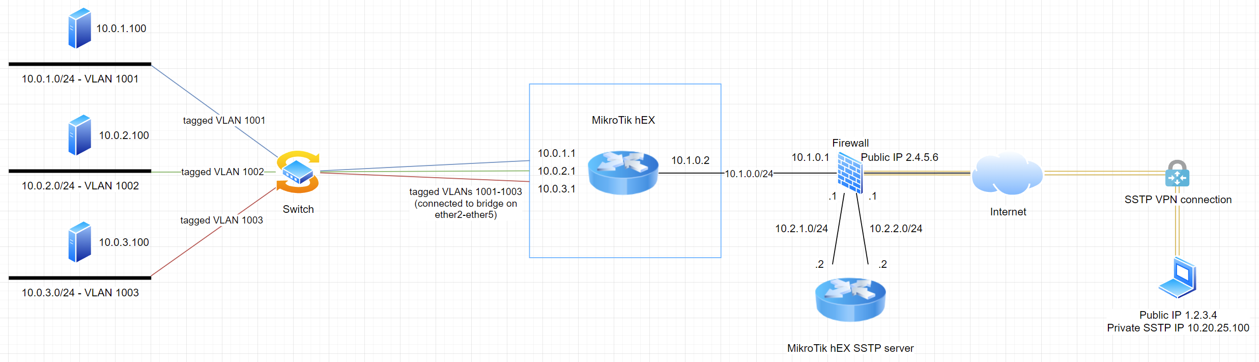
Topology overview
Note that the hEX from one of my previous posts (Clicky) is still there, we have two hEX routers in this network now! In an upcoming post I’ll explain how to do this with one single hEX router while keeping the Topology from above so we can still use our Fortigate firewall for firewalling. Hint: It will involve VRF!
For now, all VPN traffic is going to flow from the client laptop on the right, through the SSTP VPN connection to the Fortigate firewall which forwards this traffic via NAT to the 10.2.2.2 IP of our hEX SSTP server, where the tunnel terminates. From there, all traffic is being routed through the LAN side of the hEX SSTP server (10.2.1.2) to the firewall (10.2.1.1) where it will be routed further to the internal MikroTik hEX router (10.1.0.2) where the traffic will finally reach its destination.
Start by deploying a TLS certificate
For SSTP to work properly and securely, your hEX SSTP server needs a TLS certificate which is being trusted by the MikroTik router and all your potential SSTP client computers. If you want to know how to accomplish that, have a look at my previous blog post about that topic: Clicky
A standard Web Server certificate will do, make sure that you are using at least SHA256 hashing algorithm and at least a 2048 bit key. Supposedly a ECDSA_P256 certificate is even more secure and recommended for SSTP, but I’m not sure whether MikroTiks support that, so let’s stick to a RSA-2048/SHA256 certificate for now.
Name the certificate something like “SSTP-Server” and import it into your MikroTik router. Make sure, as always, that your trust chain is complete and that your CRL infrastructure works from the Internet (because clients are going to check the CRL during SSTP connection establishment).
RADIUS
Because we want proper Always On VPN without users having to enter credentials and to make use of our existing identity provider (probably Active Directory or some other LDAP server), we want to use an existing RADIUS server which authenticates against our identity provider. In this scenario I’m using Microsoft Windows NPS server (which comes included with Windows Server) but of course you can use whatever you want. Preferably configure a LDAP user group or something with all the users who are allowed to connect via SSTP VPN and then configure your RADIUS server accordingly, so that it allows connection requests from users who are a member of that group. For Windows NPS server I can tell you that you will also have to enable the MSCHAPv2 authentication method in the according network policy.
Configure the RADIUS client of your MikroTik router like this:
Choose a proper secret key and note that I have set the src-address to the LAN facing side of our SSTP router. Our firewall is only going to allow traffic from 10.2.1.2 to the NPS server 10.0.1.100, which lives all the way on the left in our VLAN 1001.
Now enable RADIUS so our hEX actually starts utilizing it for authentication requests:
/ppp aaa set use-radius=yes
Hint: If you are using Windows NPS server as RADIUS, you will have to enable NTLMv2 compatibility, if you were following general security recommendations in the past and have already disabled NTLM in your network. To do that, create a DWORD item with the name “Enable NTLMv2 Compatibility Value” and value 1 in the following path:
Now let’s create an IP pool for our SSTP clients. That pool is going to matter to our firewall, because we will be using these IP addresses to create our ruleset and to define where the SSTP VPN clients will be allowed talking to. Other than that, it doesn’t really matter which IP range you choose, just be aware that you must not overlap it with any IP subnets which are already in use in your network. In my case, I have chosen the SSTP client network to be 10.20.25.0/24 while leaving some spare addresses from .101 to .254 and leaving .1 for the router itself:
/ip pool add name=SSTP-VPN-Pool ranges=10.20.25.2-10.20.25.100
Now let’s create a PPP profile. At first I was confused why I had to create a PPP profile for SSTP but when I realized that SSTP really just tunnels PPP, it was quite obvious:
The dns-server property defines which DNS servers are going to be propagated to our SSTP clients, so enter your internal DNS servers here for proper name resolution to work. Don’t forget to create a firewall rule for that DNS traffic!
“local-address” just defines the router’s own IP address which the SSTP clients will be talking to. Note, that I have deliberately excluded that IP from the client IP pool so we don’t get any overlaps.
The parameter “only-one” makes your client users Highlanders. It allows only one connection per user account. Depending on your environment, choose what suits your requirements best.
“remote-address” defines the IP pool which will be used for your clients connections
“use-compression” and “use-encryption” I am not quite sure about. According to MikroTik documentation, use-encryption has no effect on SSTP tunnels, it still gives me the warm, fuzzy feeling though, to have it enabled. “use-compression” may or may not have an effect, I hadn’t had the chance to verify/benchmark that yet. Enabled compression may negatively affect your hEX’s CPU load, though.
Enable the SSTP server
Finally, we can enable our SSTP server on the hEX router:
/interface sstp-server server
set authentication=mschap2 certificate=SSTP-Server default-profile=SSTP-VPN-Profile enabled=yes force-aes=yes pfs=yes port=443 tls-version=only-1.2
“authentication” allows us to choose between pap, chap, mschap1 and mschap2 of which we want to use the most secure one (or rather the least insecure one), which is mschap2
“certificate” obviously sets the certificate we have created and imported earlier for the SSTP server – see here for a how to: Clicky
“default-profile” configures the SSTP server to use our previously created SSTP profile
Regarding “force-aes”, the MikroTik documentation states that Windows clients won’t be able to connect if enabled, because they only support RC4. I haven’t verified since when Windows clients support more than that, but Windows 10 20H2 is perfectly able to connect with force-aes enabled and I’ll take a wild guess and say that that’s like that for quite some years now and that MikroTiks documentation simply hasn’t been updated here.
“pfs” is another security measure you want to have enabled if possible, I’m however not sure whether Windows supports that. In my lab, the connection comes up flawlessly, however.
With “tls-version=only-1.2” we add another bit of security by disabling weak and insecure, old TLS and SSL standards like SSL 3.0, TLS 1.0 and TLS 1.1
Create routes for your traffic
To enable your SSTP client users to reach all required network destinations, you will need some routes:
The first route is our default route into the Internet, it goes through the WAN side of our hEX router (10.2.2.2). The following three routes are there for traffic to the LAN VLANs 1001-1003 to go through the LAN side of our router (10.2.1.2) to our firewall where you can define firewall rules who will be allowed to access what resources.
A little bit of firewalling on the hEX router
I would advice to block traffic from the SSTP clients to the management interfaces of your hEX router. To do that, create the following rule:
Next we need to create a VPN profile for Windows. There are several ways to do this, including Microsoft Intune or Microsoft System Center Configuration Manager (or Endpoint Manager as it is called nowadays). We are going to use a Powershell script here and the following XML file named “vpn.xml”:
Servers sstp.mydomain.com resolves to the public IP of our firewall (2.4.5.6), where traffic gets NATed to the internet-facing IP of our MikroTik hEX SSTP server (10.2.2.2).
NativeProtocolType sets the tunnel type. Possible values are PPTP, L2TP, IKEv2 and Automatic, according to Microsoft documentation. Choosing Automatic will try protocolls in following order: SSTP, IKEv2, PPTP and L2TP. Again, this is according to current Microsoft documentation.
Authentication/UserMethod can be EAP or MSChapv2 but as MikroTik does not support EAP, we have to stick with MSChapv2
RoutingPolicyType set to SplitTunnel means that only defined IP ranges which are defined later in the XML file are being routed into the VPN tunnel. ForceTunnel would mean that any traffic must go over the VPN tunnel. Choose what suits your needs, i prefer split tunneling.
DisableClassBasedDefaultRoute seems like a typical Microsoft configuration option to me. If set to yes, and the client interface IP begins with 10 (for example), a route with destination 10.0.0.0/8 will be configured for the tunnel. I prefer creating specific routes manually.
With entries like the Route ones, you can define IP subnets or hosts (when using the /32 prefix size) which should be routed over the VPN tunnel. In our example I have added the IP ranges of our internal VLANs 1001-1003.
AlwaysOn means what it says. The tunnel auto-connects upon sign in of the user until the user manually disconnects it.
TrustedNetworkDetection is a feature to prevent client computers from connecting to the VPN when they already are inside the corporate network. This checks the DNS suffix of the LAN connections of your client computer and if it finds the one specified in this setting, the VPN tunnel is prevented from connecting automatically.
DeviceTunnel set to false means that this is a UserTunnel. For an explanation about the differences see the introduction at the beginning of this post.
RegisterDNS set to true tries to register the client computers IP address of the VPN tunnel interface with the DNS servers we have supplied in the PPP profile of our MikroTik. Very handy, if you want to have all your client computers resolvable while they are on the go!
Hint: I have seen TrustedNetworkDetection sometimes to not work properly which can cause issues and unwanted behavior. To prevent clients from connecting to your SSTP server while they are within your corporate network, you can for example block access to the SSTP server from your LAN or incorporate DNS policies on your internal DNS servers which disallow internal clients to resolve your SSTP server hostname (sstp.mydomain.com) properly.
Hint 2: Further documentation on VPN profile configuration and many of the options can be found at docs.microsoft.com.
Deploy profile
Profiles can be deployed using several methods. As mentioned before we are going to do it with a Powershell script:
Only thing you need to do is to replace “vpn.xml” with the path and filename to your xml file, replace “USER-TUNNEL” with your desired VPN tunnel name and run the script.
Conclusion
We now have a MikroTik hEX router running an SSTP server for our Windows Always On clients and a template for configuring as many Windows clients as we want for Always On VPN. This can be an affordable and easy solution instead of having to license yet another Windows Server for this task. Also, we can use our favourite firewall (nobody says it has to be a Fortigate like in my case) and leverage its capabilities to let the hEX do what it can do best: routing (and SSTP-servering ;-))
Upcoming
As some of you may have only one public IP address available and SSTP now uses our valuable port 443, I’m planning to write a blog post about how to publish your hEX routers SSTP server through a HTTPS reverse proxy which allows you to use your single public IP for multiple services, all on port 443. Hint: they will be distinguished by their host name!
Also, some of you may only have one hEX router and (for incomprehensible reasons) want to keep it that way. For those of you I will write a blog post about how to isolate the SSTP server part and the internal core router part from each other using VRF.
One-Time
Monthly
Yearly
BUY ME A COFFEE (AKA Make a one-time donation)
Make a monthly donation
Make a yearly donation
Choose an amount (meh coffee, good coffee, exquisite coffee)
¤1.00
¤2.00
¤3.00
¤5.00
¤15.00
¤100.00
¤5.00
¤15.00
¤100.00
Or enter a custom amount
Your contribution is appreciated. Coffee will eventually turn into more hopefully useful posts.
For anything serious regarding TLS, you will need valid certificates. My recommended way of achieving that, would be to have a PKI infrastructure set up (e.g. with Windows Server Certification Authority) and then trust the Root and Intermediate certificates in your MikroTik devices and all your clients and servers. Obviously, if you have an Active Directory Domain, accomplishing that trust level is way easier than having to import the certificates to each and every client.
In this article we are going to assume that…
…you have a PKI infrastructure set up and ready to go
…you have your public key certificate files of your PKI servers handy (Base64 encoded), do not export the private keys!
…all your clients and servers are already trusting your PKI
…your CRL infrastructure is working, i.e. all clients and servers which are accessing resources which are using our TLS certificates, can access the CRL (including our MikroTik router)
…you don’t need public or foreign clients to trust your certificate. This guide is for a scenario where you want trusted certificates for clients and servers which are member of a private network
At the end we will have achieved the following:
Our MikroTik router will be trusting our PKI
Our MikroTik router will be checking certificates against the CRL of our PKI
We will have created a TLS certificate for the web interface of our MikroTik router and have bound it to the www-ssl service
Importing our PKI certificates
Importing trusted Root certificates is rather easy, just upload the Base64-encoded .cer file which contains the public key of your root certificate authority to your Router (e.g. using WinBox -> Files node) and import it with the following command:
If you have a two-tier PKI consisting of a root CA and an intermediate (issuing) CA, just copy the contents of both Base64-encoded files together into one file and upload and import it like above.
If everything went well, you’ll end up with something like this:
Trusted certificate authorities (two-tier)
Note that the “T” flag is present, which stands for “trusted”. Our MikroTik router now trusts all certificates which have been issued by this PKI.
Creating a new certificate for our MikroTik router
Usually, to create a new certificate for some device, we first need to create a certificate signing request (CSR), which will then be sent over to our PKI. The PKI signs the request and we import the signed request (i.e. the response) into our router.
With MikroTik routers we first need to create a so-called template, from which we subsequentially will derive our CSR:
Note the subject-alt-name parameter. This is needed for current web browsers to not show any warnings or error messages when connecting to the service. If you need more subject alternative names, just comma-separate your entries (without any spaces).
Note that the chosen name must be DNS-resolvable and that it must be the actual name you are using when accessing your router using the web interface, otherwise your browser will keep throwing certificate warnings at you.
Choose something different instead of “myRandomPassword”. This is the password for the private key of your certificate. You want to keep it secret and secured.
Sign the certificate request using your PKI
Now you need to download the “certificate-request.pem” file which has now been created from your MikroTik router and sign it using your PKI. I will not be showing this here because covering every PKI solution would be out of scope for this post and I’m just going to assume that you know how to operate your PKI if you have one.
Upload and import
Upload the signed certificate file to your MikroTik (let’s assume it is called certificate.cer) and import it using the following command:
Now we need to configure the www-ssl service to use the new certificate and then enable it.
/ip service set www-ssl certificate=www-ssl-Server disabled=no
Also, don’t forget to restrict access to only specific source addresses (that applies to ALL services!):
/ip service set www-ssl address=1.2.3.0/24,2.3.4.0/24
Note, that you can specify multiple IP addresses and ranges by separating them using commas, like in the example above.
Conclusion
We have now configured our MikroTik router to trust our Enterprise PKI and we have created a trusted TLS certificate for the www-ssl service of our router so you a) don’t get any more warnings when accessing the web interface and b) you notice immediately if there is any man in the middle attack (aka SSL inspection) going on.
This procedure can be used to create certificates for any service with TLS support on the MikroTik router, like SSTP VPN server for example.
One-Time
Monthly
Yearly
BUY ME A COFFEE (AKA Make a one-time donation)
Make a monthly donation
Make a yearly donation
Choose an amount (meh coffee, good coffee, exquisite coffee)
¤1.00
¤2.00
¤3.00
¤5.00
¤15.00
¤100.00
¤5.00
¤15.00
¤100.00
Or enter a custom amount
Your contribution is appreciated. Coffee will eventually turn into more hopefully useful posts.
Today I wanted to install a MikroTik hEX router into my lab environment to act as a core router (without NAT), one hop before my firewall (see diagram below).
MikroTik hEX as core router
So in a scenario like this, we want the hEX to be a router to allow intra-VLAN routing between the VLANs 1001, 1002 and 1003. Of course, the hardware firewall in our diagram could probably do that for us as well, but that’s not always something one wants or needs or maybe the firewall in charge even isn’t as capable in terms of throughput and one doesn’t want to put that additional load of potentially full Gigabit between the VLANs on it. In this scenario I didn’t plan for any firewalling on the hEX router but we could, in theory, deploy some ACLs which should be processed in hardware (iirc) to allow for some segregation in our segmentation 😉
Also, using a second router to hold all our internal VLANs gives us a separated routing instance which might come in handy with later, more complex scenarios. Not to mention the security benefit of being able to create VLANs and networks for DMZ purposes on the internet-facing firewall which effectively means that traffic literally wouldn’t even aim towards a physical cable leading to your internal network, but staying physically (on Layer 2) behind a firewall, where external traffic belongs. We all do that like this, right? Right?
While being extremely powerful and versatile, the correct configuration for a specific tasks doesn’t always appear obvious with MikroTik devices. Sometimes it even depends on the type of hardware MikroTik is using for a given device model. MikroTik has tons of documentation on everything but still, this took me two or three hours to figure out, being a complete newcomer to anything labeled MikroTik.
The solution
Now, enough of the babbling. In this scenario, we have configured bridge1 to contain the interfaces ether2-ether5, leaving ether1 separated for the WAN side of the router. You could in theory use ether2-ether5 as separate interfaces, all with their own VLANs but in this case I wanted to run all VLANs through a single cable regardless of which port (ether2-ether5) I connect the uplink cable to. In theory, we could do some port aggregation later on, running all VLANs through some port-aggregated uplink. For now, this is a classical router layout where you have a LAN side switch with some ports (ether2-ether5) and one WAN port (ether1).
Because as of firmware 6.48.6* the hEX does not support VLAN filtering on the bridge level while keeping hardware offloading enabled, the approach here is a bit different than on other devices like the CRS3xx switch series. For the hEX router (in fact for any device using the MT7621 chipset) we need to configure the VLANs on the “Switch/VLAN” level instead. Note: switch1-cpu needs to be a member of all VLANs for routing to work properly. It is recommended to implement appropriate firewall rules to prevent unwanted access to the router (we will cover that later below).
* According to MikroTik documentation as of writing this post, Bridge VLAN Filtering in hardware has been added in RouterOS 7.1rc5 for MT7621 based devices
Set VLAN mode to “secure” for our LAN interfaces so only appropriately tagged traffic can enter the so secured ports. Other traffic will be dropped.
/interface ethernet switch port
set 0 default-vlan-id=1 vlan-mode=fallback
set 1 default-vlan-id=1 vlan-mode=secure
set 2 default-vlan-id=1 vlan-mode=secure
set 3 default-vlan-id=1 vlan-mode=secure
set 4 default-vlan-id=1 vlan-mode=secure
set 5 default-vlan-id=1 vlan-mode=secure
Additionally, we need to disable any spanning-tree protocol on the bridge, otherwhise hardware offloading will get disabled.
/interface bridge set protocol-mode=none
Interfaces for all VLANs have to be created, so we can assign IP addresses to them and actually start routing data:
Now lets restrict traffic to the management services a bit and disable some legacy services. It is advised to create an SSL certificate and only manage over encrypted protocols like https or api-ssl. We could as well create some firewall filter rules to lock the router down even more but for now let’s start with this. Let’s assume that 10.0.1.0/24 is our management VLAN, so access to the management services is only allowed from there. Keep in mind, that we are restricting the source IPs of the management traffic, so if you are on a management workstation which has e.g. the IP address of 10.0.1.100, you can still access the router on 10.0.2.1 and 10.0.3.1 because traffic is being routed from 10.0.1.100 (which is still the source of the request and therefore allowed) to 10.0.2.1 or 10.0.3.1. Restricting management traffic to 10.0.1.1 only would require firewall filtering rules or configuring the management services not to listen on the other interfaces (which I am not aware of whether that’s possible).
/ip service
set telnet address=10.0.1.0.0/24 disabled=yes
set ftp address=10.0.1.0/24 disabled=yes
set www address=10.0.1.0/24
set ssh address=10.0.1.0/24
set www-ssl address=10.0.1.0/24 tls-version=only-1.2
set api address=10.0.1.0/24 disabled=yes
set winbox address=10.0.1.0/24
set api-ssl address=10.0.1.0/24 disabled=yes
Note, that even disabled services have their allowed address range configured, just as a good measure.
Now let’s organize our interfaces into two lists (LAN and WAN) and restrict access to the MAC server and MAC Winbox only to internal interfaces:
/interface list
add name=WAN
add name=LAN

/interface list member
add interface=bridge list=LAN
add interface=VLAN1001 list=LAN
add interface=ether1 list=WAN

/tool mac-server
set allowed-interface-list=LAN
/tool mac-server mac-winbox
set allowed-interface-list=LAN
Results
As you can see below, this configuration leads to active hw-offload on the bridged interfaces:
Hardware offload is active
Here we can see a throughput of around 800 Mbits/sec with one single stream via iperf3. The CPU load on the hEX was around 20% during the iperf run:
Throughput of around 800 Mbits/sec with one single stream
Conclusion
Proper configuration of the hEX router and making use of its hardware features allows us to achieve high throughput rates without running into the limits of the CPU. This post does not claim to be a complete guide for setting up a hEX router, many more configuration options may apply to your environment. AFAIK, MikroTik also recommends to enable Ingress Filtering on the Bridge Ports to increase security, but I haven’t digged into that yet.
If you have any suggestions, improvements or any other feedback, leave it in the comments down below.
One-Time
Monthly
Yearly
BUY ME A COFFEE (AKA Make a one-time donation)
Make a monthly donation
Make a yearly donation
Choose an amount (meh coffee, good coffee, exquisite coffee)
¤1.00
¤2.00
¤3.00
¤5.00
¤15.00
¤100.00
¤5.00
¤15.00
¤100.00
Or enter a custom amount
Your contribution is appreciated. Coffee will eventually turn into more hopefully useful posts.